
| Version 5 (modified by , 11 years ago) (diff) |
|---|
Describing And Manipulating Experiment Topologies in DETER
This page describes the model, specification and implementation of DETER's topology description. A topology is the layout of an experment's physcial or logical environment including the topologies of its control and data networks.
Because DETER experiments are intended to be large - thousands or millions of entities - DETER's topology system must support large scale
- Specification
- Operations - realize, initialize, etc.
- Visualization
We describe a model that suports these, an API that describes how to use the model and an initial implementation in the Descartes interface.
Model
The Basic Model
A DETER topology is a collection of experimental elements that can communicate with one another. The topology model consists of elements that represent those experimental entities and substrates which indicate the valid commuincations scopes. An element may be specialized depending on the capabilities supplied or required. A substrate includes limits on how the communication rate and delay when communicating through it.
The topology is represented as a bipartite graph where vertices are either substrates or elements. Edges are interfaces. Each interface connects an element to a substrate, indicating that the element can communicate on the substrate. An element may have additional communication constraints encoded in it as well.
Each element and each substrate has a unique name in the topology. Each interface also has a name, scoped by the element it connects to.
We stress that these are logical descriptions. Within DETERlab a substrate is usually realized as a virtual LAN (VLAN), but a substrate in general may capture a VLAN, a shared WDM frequency, a microwave line-of-sight or an open window across an alley. Similarly, an interface may represent a single card in a computer or a specific radio configuration. The mapping of interfaces or substrates to physical items is not always one-to-one. Similarly elements are logical communicating entities. They are specialized by the basic role they play in the experiment. Currently the most commonly encountered element is a computer, which may be a physical machine, a virtual machine instance, or even a process.
Element specialization is a fairly heavyweight extensbility mechanism. A simpler one is the ability to attach attributes to elements, substrates, interfaces, and the various sub components of specialized elements. Attributes are named strings where the names are scoped by the thing they are attached to. This allows tools that construct or manipulate topologies to annotate the topologies even if the core testbed does not use the information.

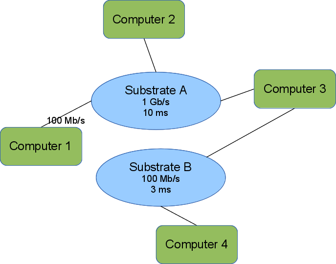
The image shows a simple topology encoded in our topology model. Computers 1,2, and 3 can communicate directly because they each have an interface on Substrate A. We omit the interface names. Computers 2 and 3 can send as fast as 1 Gb/s but experience a 10 ms delay before the first bit transmitted arrives at the receiver. Computer 1 is further constrained by its interface to a rate of 100 Mb/s, but sees the same delay.
Computers 3 & 4 can also communicate directly over Substrate B.
Computers 1 & 2 cannot communicate with Computer 4 unless Computer 3 forwards messages.
This also shows the bipartite nature of the graph. Substrates (blue ellipses) are only connected to computers/elements (green rounded rectangles). All interfaces connect an element to a substrate.
Scaling Using Regions and Fragments
The basic model specifies communication networks at a fairly high degree of abstraction while maintaining mechanisms for specialization. However, large topologies present several problems:
- Storing and transferring the entire topology can be wasteful if the researcher is only interested in manipulating or viewing parts of it
- There is no effective way to annotate subgraphs of the topology, though this is a natural way for researchers to specify and manipulate complex topologies
- There is no way to specify subgraphs of a topology beyond enumerating them
The region element addresses these shortcomings. A region is a placeholder in a topology that stands in for a subgraph, called a fragment. The region includes a natural language description of the missing subgraph and provides enough detail on how to generate the missing fragment. Note that fragments may also contain regions.
Fragments are specified outside the topology description. In fact, a fragment is exactly a topology description, so fragments can be combined easily.
A region specifies the fragment that it is standing in for by name. That name may be a pointer into a larger data structure that includes a fragment pool or a pointer to a service that can provide the fragment. Each region contains rules mapping the region's interfaces to elements in the fragment (of course the region's interfaces cannot be mapped to substrates in the fragment, because that would violate the bipartite rules of the graph).
In order to keep the names unique in the fully expanded topology, each region also contains rules used to rename the fragment elements and substrates when the region is expanded. There is some complexity to this that we expand on below.
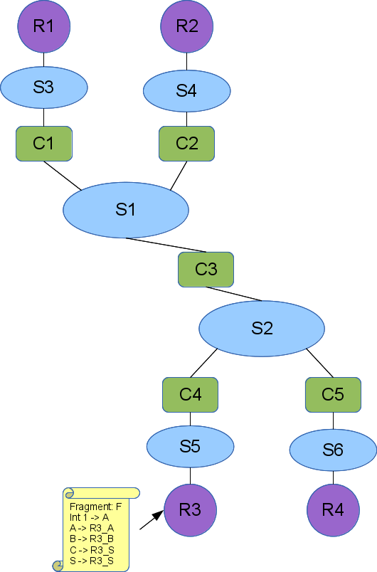
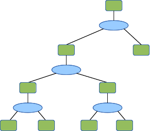
Here is a small topology with several regions defined:

This could be a wide are network with the leaf enterprise networks (or next tier wide area networks) replaced with regions (the magenta circles). We have shown the expansion rules attached to region R3. It will be replaced by a fragment named F, where R3's interface (int1) will connect to the element named A in fragment F. When the region is replaced, the elements A, B, and C in F will be replaced with R3_A, R3_B, and R3_C to maintain their uniqueness. We do not show the expansion rules for the other regions, but they follow this convention of prepending the region name.
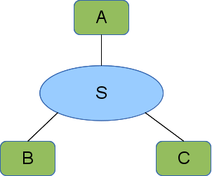
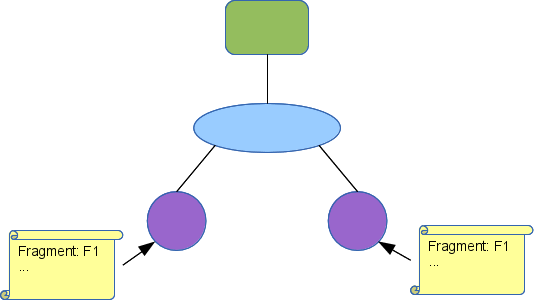
Fragment F looks like this:

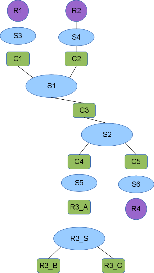
So that when R3 is expanded the overall topology looks like this:

Recursive Regions
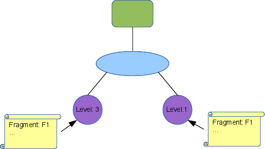
Fragments can contain regions, so topology descriptions can be recursive. These topology descriptions are used to allocate testbed resources, so the model insures that all recursions terminate. Each region is assigned a non-negative integer valued level. The outermost specification of topology can has region levels assigned by the user. When a region is inserted into a topology as a member of a fragment that replaces a region, we assign all regions in that replacement a level one less than the region that was expanded.
This is probably more intuitive with an example. Here is a topology:
Attachments (9)
-
Simple_topo.png (51.5 KB) - added by 11 years ago.
Simple topology
- Fragment.png (11.9 KB) - added by 11 years ago.
- Unexpanded.png (68.4 KB) - added by 11 years ago.
- Expanded.png (71.5 KB) - added by 11 years ago.
- Recursion.png (18.5 KB) - added by 11 years ago.
- Recursion_Frag.png (17.6 KB) - added by 11 years ago.
- Recursion1.png (10.9 KB) - added by 11 years ago.
- Recursion2.png (14.2 KB) - added by 11 years ago.
- Recursion3.png (13.6 KB) - added by 11 years ago.
Download all attachments as: .zip