
| Version 8 (modified by , 14 years ago) (diff) |
|---|
For our example, we are configuring a HP 2810-48G switch. These commands should also work with the HP5400zl series.
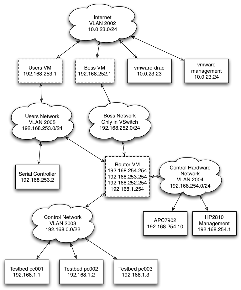
Network Overview
There are a number of different networks and hosts involved with a traditional Emulab setup.
For servers, we will have three machines hosted on a VMWare server:
- Boss hosts the web interface, main testbed logic, and database.
- Users exports filesystems and acts as a general login machine.
- Router routes between the various networks.
We also have on the network:
- HP 2810 Ethernet Switch Management Interface
- Dell Remote Access Card for VMWare server
- VMWare management interface
- Power Controller (APC7902)
- Serial Controller (IBM X330 + Obsolete Cyclades multi-port serial card)
Initial Ports
| Port | Device |
| 1 | Uplink to Internet |
| 2 | Port for Dell Remote Access Card (DRAC) for the VMWare server (PowerEdge 2950) |
| 3 | Trunked port for the VMWare installation on the PowerEdge 2950 |
| 4 | APC 7902 Power Controller |
| 5 | Serial Controller |
| 6-9 | Control Network ports for our testbed nodes |
VLANS
| VLAN | IP Range | Use |
| 2002 | Depends (our minibed is behind a NAT on 10.0.23.0/24) | Internet VLAN |
| 2003 | 192.168.0.0/22 | Control Network VLAN |
| 2004 | 192.168.254.0/24 | Control Hardware VLAN |
| 2005 | 192.168.253.0/24 | Users Network |
| 2006 | 192.168.252.0/24 | Boss Network |
Diagram

Switch Configuration
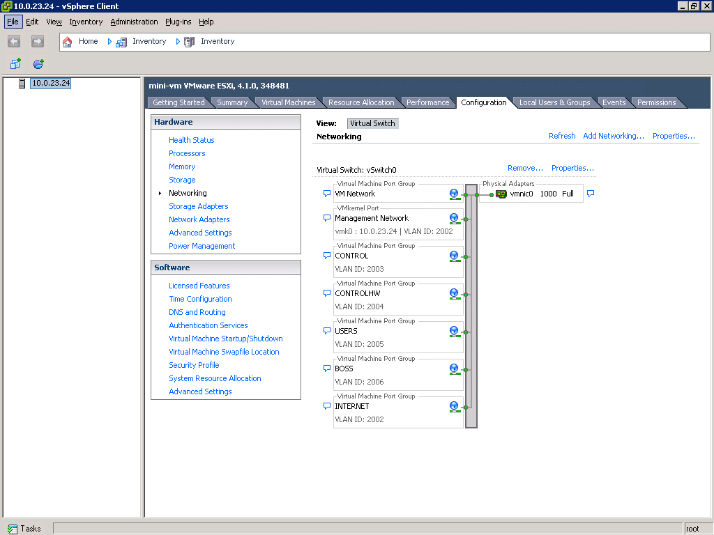
VMWare Network Setup
For the minibed at ISI, the VMWare ESXi server is on a single trunked port.

Boss VM
- em0 is on INTERNET
- em1 is on BOSS
Users VM
- em0 is on INTERNET
- em1 is on USERS
Router VM
- em0 is on USERS
- em1 is on BOSS
- em2 is on CONTROL
- em3 is on CONTROLHW
Attachments (4)
- Mini DETER Network.png (170.4 KB) - added by 14 years ago.
- vmware_network.PNG (46.2 KB) - added by 14 years ago.
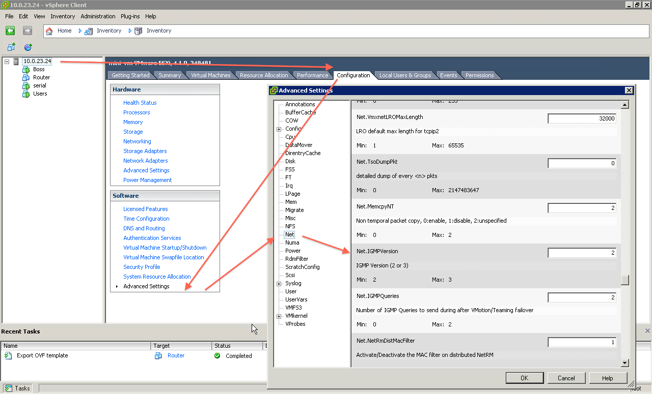
- vSwitch IGMP.png (102.7 KB) - added by 13 years ago.
-
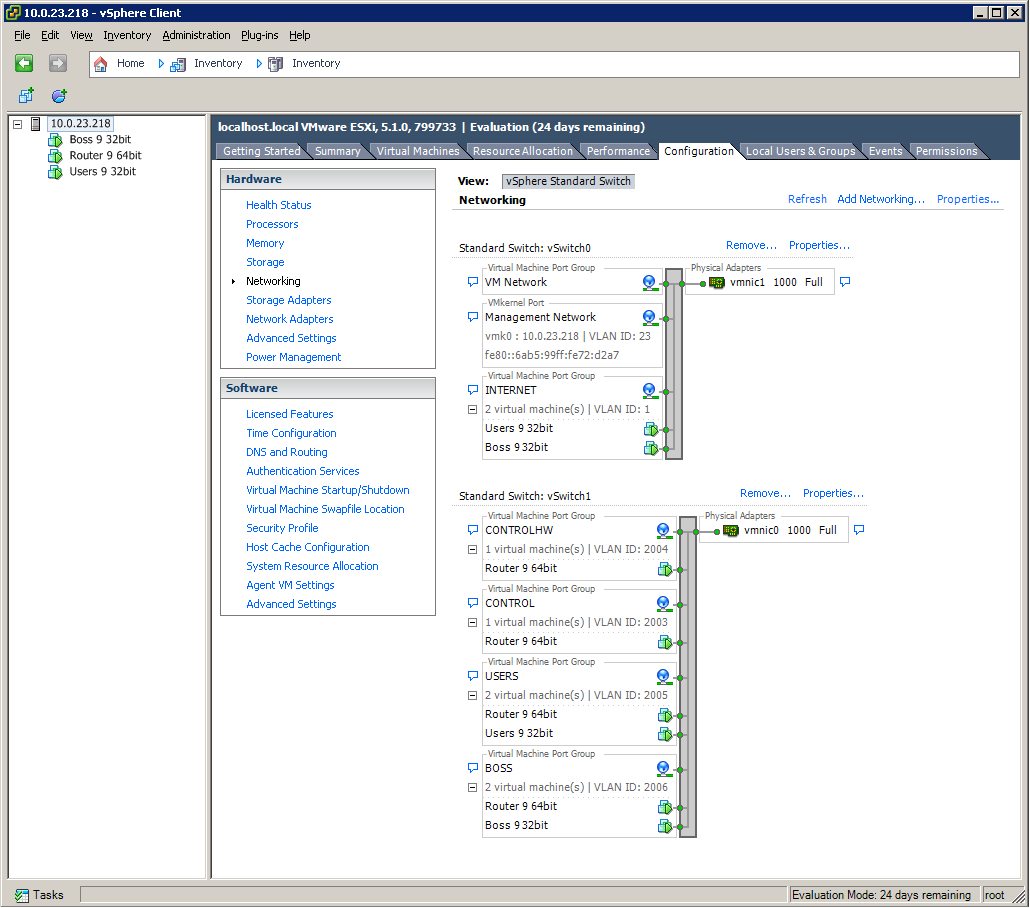
Two NIC ESXi.png (67.5 KB) - added by 12 years ago.
Example of ESXi with two NICs
Download all attachments as: .zip