Table of Contents
For our example, we are configuring a HP 2810-48G switch. These commands should also work with the HP5400zl series.
Keep in mind, this is an example configuration. You site may:
- Not require full remote access to your ESXi machine (no DRAC or iLO connection).
- Use IPMI in place of Serial and Power controllers.
A note about public IP addresses for boss and users
We will be unable to offer your site support if you do not setup your boss and users nodes with public IP addresses. Although the setup below is using NATed addresses, your chances for a quick and easy cluster setup go down dramatically when you do not allocate two public, static IP addresses for boss and users. Using DHCP for the public interfaces of your testbed will cause numerous problems because it changes routing and DNS in ways that are incompatible with the DETER software. We have limited resources and debugging is best performed in real time with remote access to your cluster.
Network Overview
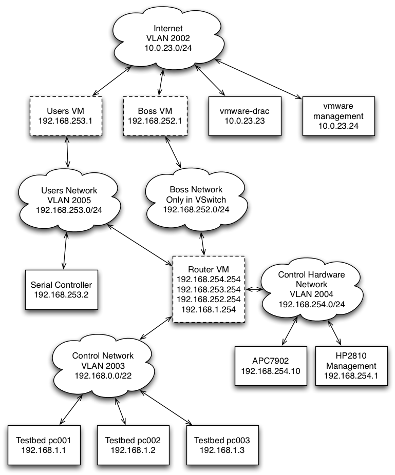
There are a number of different networks and hosts involved with a traditional Emulab setup.
For servers, we will have three machines hosted on a VMWare server:
- Boss hosts the web interface, main testbed logic, and database.
- Users exports filesystems and acts as a general login machine.
- Router routes between the various networks.
We also have on the network:
- HP 2810 Ethernet Switch Management Interface
- Dell Remote Access Card for VMWare server
- VMWare management interface
- Power Controller (APC7902)
- Serial Controller (IBM X330 + Obsolete Cyclades multi-port serial card)
Initial Ports
| Port | Device |
| 1 | Uplink to Internet |
| 2 | Port for Dell Remote Access Card (DRAC) for the VMWare server (PowerEdge 2950) |
| 3 | Trunked port for the VMWare installation on the PowerEdge 2950 |
| 4 | APC 7902 Power Controller |
| 5 | Serial Controller |
| 6-9 | Control Network ports for our testbed nodes |
VLANS
Here is the list of reserved VLANs used by DETER.
| VLAN | IP Range | Use |
| 2002 | Depends (our minibed is behind a NAT on 10.0.23.0/24) | Internet VLAN |
| 2003 | 192.168.0.0/22 | Control Network VLAN |
| 2004 | 192.168.254.0/24 | Control Hardware VLAN |
| 2005 | 192.168.253.0/24 | Users Network |
| 2006 | 192.168.252.0/24 | Boss Network |
| 2007 | 192.168.224.0/20 | Node IPMI Network (On smaller sites, IPMI can be done via the Control Hardware VLAN) |
Diagram
Here is an example diagram of a very small DETER setup. It uses a traditional power controller and serial console server. Newer small sites will have IPMI contollers located on the Control Hardware network to enable remote console and power control of the testbed nodes.
Switch Configuration
Here is the configuration from the HP Procurve 2810 at the ISI mini testbed. Please note that the max-vlans number can be, and should be, increased on switches that are capable of more (5400 series). We use a trunked interface (port 3) to hook into our VMWare ESXi server.
Also make sure spanning tree is turned off. Experimental traffic shaping relies on bridging ports between VLANs.
hostname "hp1"
max-vlans 256
interface 1
   name "UPLINK"
exit
interface 2
   name "VMWARE_DRAC"
exit
interface 3
   name "VMWARE"
exit
interface 4
   name "POWER_CONTROLLER"
exit
interface 5
   name "SERIAL_CONTROLLER"
exit
ip default-gateway 192.168.254.254
snmp-server community "public" Unrestricted
snmp-server community "private" manager Unrestricted
vlan 1
   name "DEFAULT_VLAN"
   untagged 13-48
   no ip address
   no untagged 1-12
   exit
vlan 2003
   name "CONTROL"
   untagged 6-12
   tagged 3
   ip igmp
   exit
vlan 2004
   name "CONTROLHW"
   untagged 4-5
   ip address 192.168.254.1 255.255.255.0
   tagged 3
   exit
vlan 2002
   name "INTERNET"
   untagged 1-2
   tagged 3
   exit
vlan 2006
   name "BOSS"
   tagged 3
   ip igmp
   exit
management-vlan 2004
VMWare Network Setup
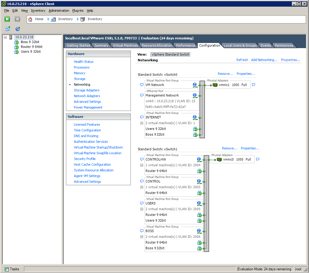
Here is an example of using two NICs. One NIC is connected to the Internet and the other is connected to the testbed switch.
Boss VM
- em0 is on INTERNET
- em1 is on BOSS
Users VM
- em0 is on INTERNET
- em1 is on USERS
Router VM
- em0 is on USERS
- em1 is on BOSS
- em2 is on CONTROL
- em3 is on CONTROLHW
HP Switch IGMP debugging
minibed# show ip igmp

 Status and Counters - IP Multicast (IGMP) Status

 VLAN ID : 1
 VLAN Name : DEFAULT_VLAN
  IGMP is not enabled

 VLAN ID : 2
 VLAN Name : _5
  IGMP is not enabled

 VLAN ID : 2003
 VLAN Name : CONTROL
 Querier Address : 192.168.1.254

  Active Group Addresses Reports Queries Querier Access Port
  ---------------------- ------- ------- -------------------

 VLAN ID : 2004
 VLAN Name : HWCONTROL
  IGMP is not enabled

 VLAN ID : 2005
 VLAN Name : USERS
  IGMP is not enabled

 VLAN ID : 2006
 VLAN Name : BOSS
 Querier Address : 192.168.252.254

  Active Group Addresses Reports Queries Querier Access Port
  ---------------------- ------- ------- -------------------
  234.5.6.30             29      29      48


minibed#
If either the BOSS vlan or CONTROL vlan show up without IGMP support, you can enable it:
minibed# config
minibed(config)# vlan 2003
minibed(vlan-2003)# ip igmp
minibed(vlan-2003)# vlan 2006
minibed(vlan-2006)# ip igmp
minibed(vlan-2006)# exit
minibed(config)# exit
minibed# write memory
minibed#
Setting vSwtich IGMP Version
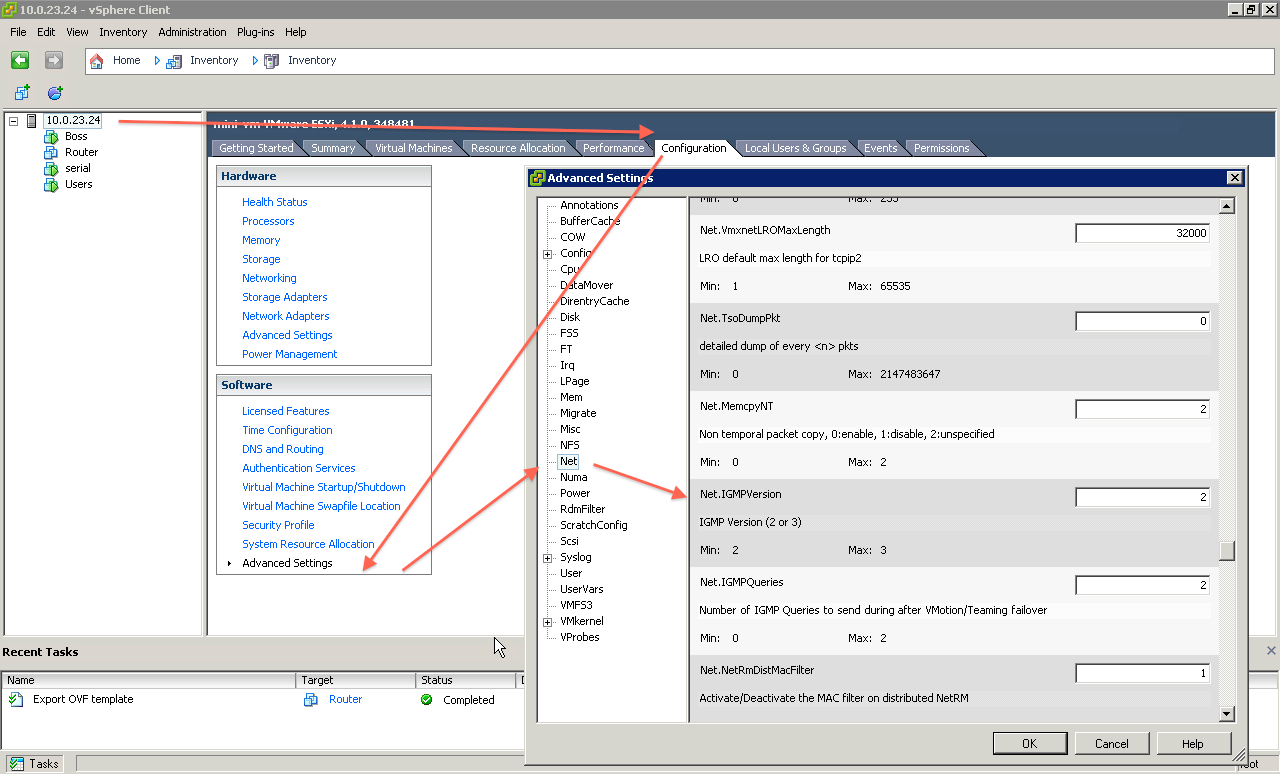
I am not sure if this is necessary. ESXi defaults to IGMP version 3. We currently need IGMP version 2 support on our vSwitch. The enable this, follow the following steps in the vSphere client:
- Click on the server
- Click on the "Configuration Tab"
- Click on "Advanced Settings" in the "Software" group
- Select "Net" in the "Advanced Settings" dialog box tree
- Set "Net.IGMPVersion" to "2"
Attachments (4)
- Mini DETER Network.png (170.4 KB) - added by 14 years ago.
- vmware_network.PNG (46.2 KB) - added by 14 years ago.
- vSwitch IGMP.png (102.7 KB) - added by 14 years ago.
-
Two NIC ESXi.png (67.5 KB) - added by 12 years ago.
Example of ESXi with two NICs
Download all attachments as: .zip


